Creo 2 0 Sheet Metal Bend

Sheet Metal Design Intent Objects For Sheetmetal Design Ptc Learning Connector

Creo Parametric Sheetmetal Bends Part 1 Youtube

Sheetmetal Flat Pattern Preview Window In Creo Parametric Flats Patterns Pattern Parametric

Twist Command Sheet Metal Creo 2 0 Youtube

Creo Parametric Sheetmetal Punch Forms Tutorial Youtube

Sheet Metal Modeling And Drawing In Creo Youtube

Selecting a bend editing option.
Creo 2 0 sheet metal bend.
Allowance Tables And Formulas

Add Flat Pattern In Sheet Metal Drawings Creo Parametric 5 0 Youtube

Solidworks Tutorial Folding And Unfolding Sheet Metal Bends By Solidwize
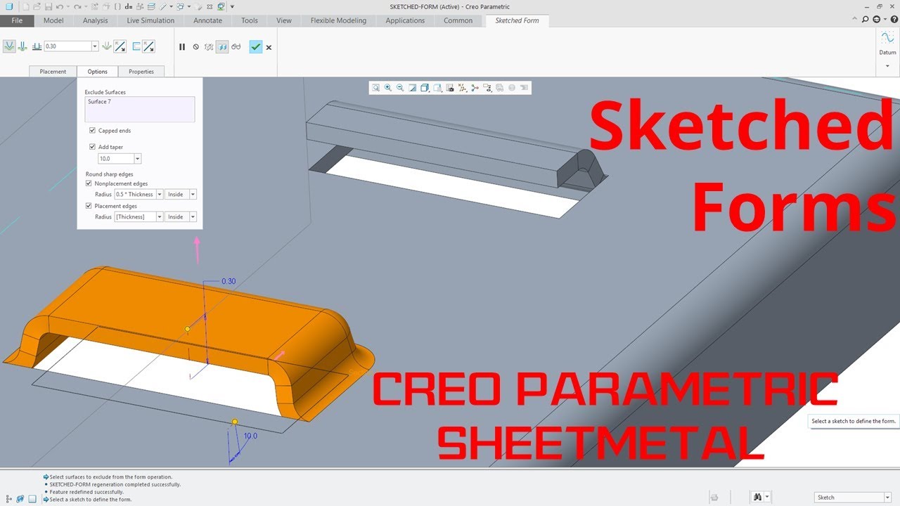
Creo Parametric Sheetmetal Sketched Forms Tutorial Youtube

Creo Parametric Sheetmetal Planar Bends Youtube

V Posledovatelnyh Shtampah Soderzhatsya Neskolko Standartnyh Chastej V Dannom Video Pokazyvaetsya Kak Eti Chasti Mogut Byt Dobavleny V Bazu Ads Progress Library

Pin On Ew

Creo Parametric Sheetmetal Design Boundary Systems Pushing The Limits Of Product Development

Flapping Wing Mechanism1 Mechanical Engineering Mechanic Engineering

Solidworks Sheet Metal Drawing Tutorial Bend Line Flat Pattern Unfolded Bend Table Punch Table Youtube
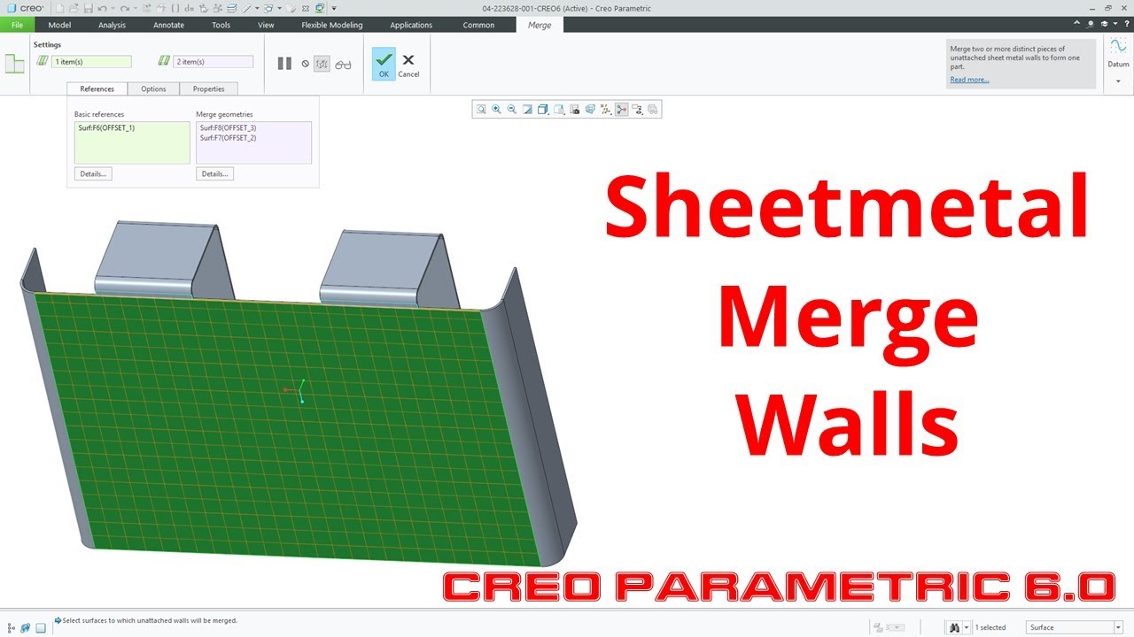
Creo Parametric 6 0 Sheetmetal Merge Walls Youtube

Creo Parametric 6 0 Sheetmetal Flat And Flange Wall Changes Youtube

Precise 2 Unfold Sheet Metal Model In Autocad Sample 3 Youtube

Creo Sheet Metal Unbend With References Deformations Distinct Areas In Creo Parametric Youtube

Flange All Types Command In Creo Sheetmetal Youtube

Complex Sheet Metal Parts Made Easy In Solidworks Youtube

Fillet In Solidworks By Smart Corner بالعربي Solidworks Corner Smart

Intro To Surface Design 2 Solidworks Tutorials Surface Design Solidworks Tutorial Solidworks Tutorial
Https Encrypted Tbn0 Gstatic Com Images Q Tbn 3aand9gcshvsmiewf8zz0llvgus01kk2qa0shi6v Iyk6p6dkf1rva6h9v Usqp Cau

Design And Build An English Wheel English Wheel Metal Furniture Design Sheet Metal Tools

Watch Webcast Replay Sheetmetal Tips And Tricks

My Opinions On Sheetmetal Autodesk Community Community Archive Read Only

Sheet Metal Convert Solid To Sm Autodesk Community

Creo Sheet Metal Project Box Youtube
Source : pinterest.com
