Creo Sheet Metal Lance

Introduction To Drawings In Creo Parametric 2 0 Parametric Solidworks Getting Things Done

Advanced Modeling In Creo 3d Model Mechanical Design Model

Learn Creating Complex 3d Models Solidworks Interview Tool Test Solidworks Tutorial Solidworks 3d Model

Sw 3d Modeling Practice 3d Modeling Tutorial Technical Drawing Autocad Drawing
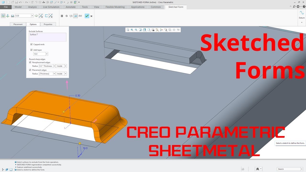
Creo Parametric Sheetmetal Sketched Forms Tutorial Youtube

Belt Chain For Conveyor In Solidworks Youtube Solidworks Conveyor Videos Tutorial

The die form workflows and user interface have been enhanced and modernized in ptc creo 3 0 so they are consistent with those of the punch form tool.
Creo sheet metal lance.

Punch Form Features Ptc Learning Connector

Pin On Laser

Pin On Mechanical Cad Services
Create Stamp Features With Stamp Tools

Creo Parametric Sheetmetal Forms From Ptc Tutorial Youtube
Creo Sheet Metal Rip Flange Split Area On Flat Wall In Creo Parametric Youtube

Sheet Metal Design Siemens Solid Edge Tutorial Youtube

Creo 5 0 Tutorial Punch Or Die Form Feature Youtube

Design Of Jigs Fixtures And Press Tools Pdf Download In 2020 Jigs False Book Tool Design

Pin Oleh Miki Di Desenhos Desainer Latihan Logam

Sheet Metal Practice Drawing In 2020 Drawing Practice Youtube Drawing Solidworks

My Opinions On Sheetmetal Autodesk Community Community Archive Read Only

Planar Model Architecture Model Architectural Sculpture Installation Architecture

12 X 10 Gauge Sheet Metal Roller Slip Roll Rolling Metalworking Brass Steel Metal Bending Tools Sheet Metal Roller Sheet Metal Tools

Solidworks Sheet Metal Forming Tool Exercise Youtube Solidworks Sheet Metal Solidworks Tutorial

Hey Ssc I M In The Process Of Completing A Slingshot Knots Guide I D Love Your Input And Feedback Though I Ll Be Addin Diy Slingshot Knots Guide Knots

Dkny Ad New York By Tomhopkinson On Deviantart Dkny Ad New York By Edgeman13 On Deviantart Dkny Perspective Art Architecture Sketch Architecture Drawing

Grace Ful Things Green Door Unique Doors Gorgeous Doors
Https Encrypted Tbn0 Gstatic Com Images Q Tbn 3aand9gctwb5x7hvkv9mszlqvpgjwexlu79fztua2 Cnzlv0fjlxaai4yz Usqp Cau

Vacation Journal Writing Catching Foxes Travel Journal Pages Vacation Journal Travel Scrapbook

Under Hood Fuse Box Diagram Ford F 250 F 350 F 450 F 550 2013 2014 2015 Fuse Panel Fuse Box F250

Joyas De Sybarite Jewellery Funky Rings Silver Plated Jewelry Jewelry

Joyas De Sybarite Jewellery Funky Rings Silver Plated Jewelry Jewelry

1920 Hen Party Favours Swan So Sweet Hen Party Hen Party Favours Great Gatsby Theme
Source : pinterest.com
